solidworks flow simulation boundary conditions
If the Pressure Potential option is not properly addressed it can lead to. In this article we set up and solved a flow problem from a solid model.

Solidworks Flow Simulation How Can Cad Integrated Cfd Tool Fulfill Your Analysis Needs Youtube
Ill cover the boundary conditions shortly but at this point I could use a hand calculation to solve for the linear thermal expansion of the cube Figure 4.

. Faster Results with Boundary Conditions. SOLIDWORKS Flow Simulation allows a designer to take advantage of. With a little bit intuition and help from SOLIDWORKS.
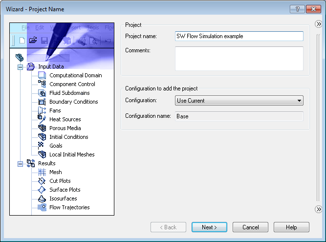
SOLIDWORKS Flow Simulation offers a wizard to direct the setup including the selection of material properties. It uses the SOLIDWORKS modeling engine to define the physical geometry and then the Flow Simulation environment defines boundary conditions and examines simulation results. There are two things you can check in your model.
By Suman Sudhakaran on January 7 2019. Flow Simulation Boundary Conditions. Boundary conditions computation domain and PDF Solidworks Tutorial Beginner Flow Simulation January 1st 2021 - Solidworks Tutorial.
SOLIDWORKS Flow Simulation Error. This question has a validated answer. To apply symmetry.
Below are the selections for this example analysis. I am performing flow analysis on a low speed low pressure high flow turbine pump and feel i have the entire concept of simulation wrong. JT By Jacob Trieu 122210.
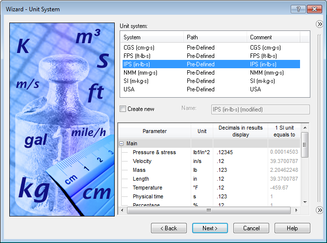
Page 3 Choose analysis type. Page 2 Set the units. Face is not laying on the boundary between the solid and fluid region.
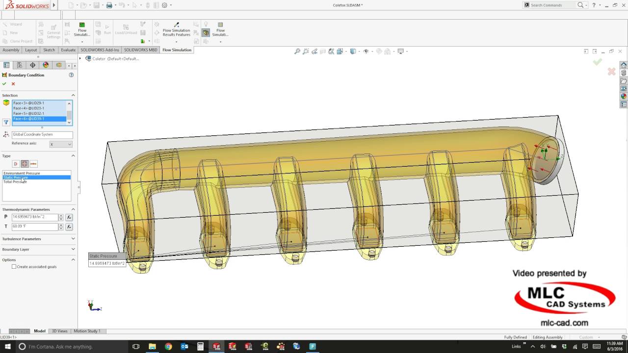
However when I click on the face of the lid I am trying to set the boundary condition. The starting point of any heat transfer analysis is to define the overall boundary conditions of the problem. SolidWorks Simulation is only helpful if the user can realistically depict component interaction.
Solidworks flow simulation tutorial pdf 26022016 Solving CFD Problems using SolidWorks Flow Simulation. With the CAD modeling complete I then turned to SOLIDWORKS Flow Simulation to study the aerodynamics. SI unit system the only thing we will be changing is the Temperature parameter from K to ºC.
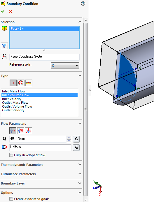
Uses flow rate mass as the flow metric. To define a boundary condition. Utilize Symmetry boundary conditions on parts with symmetric inlets and outlets to save time and effort in Simulation Flow.
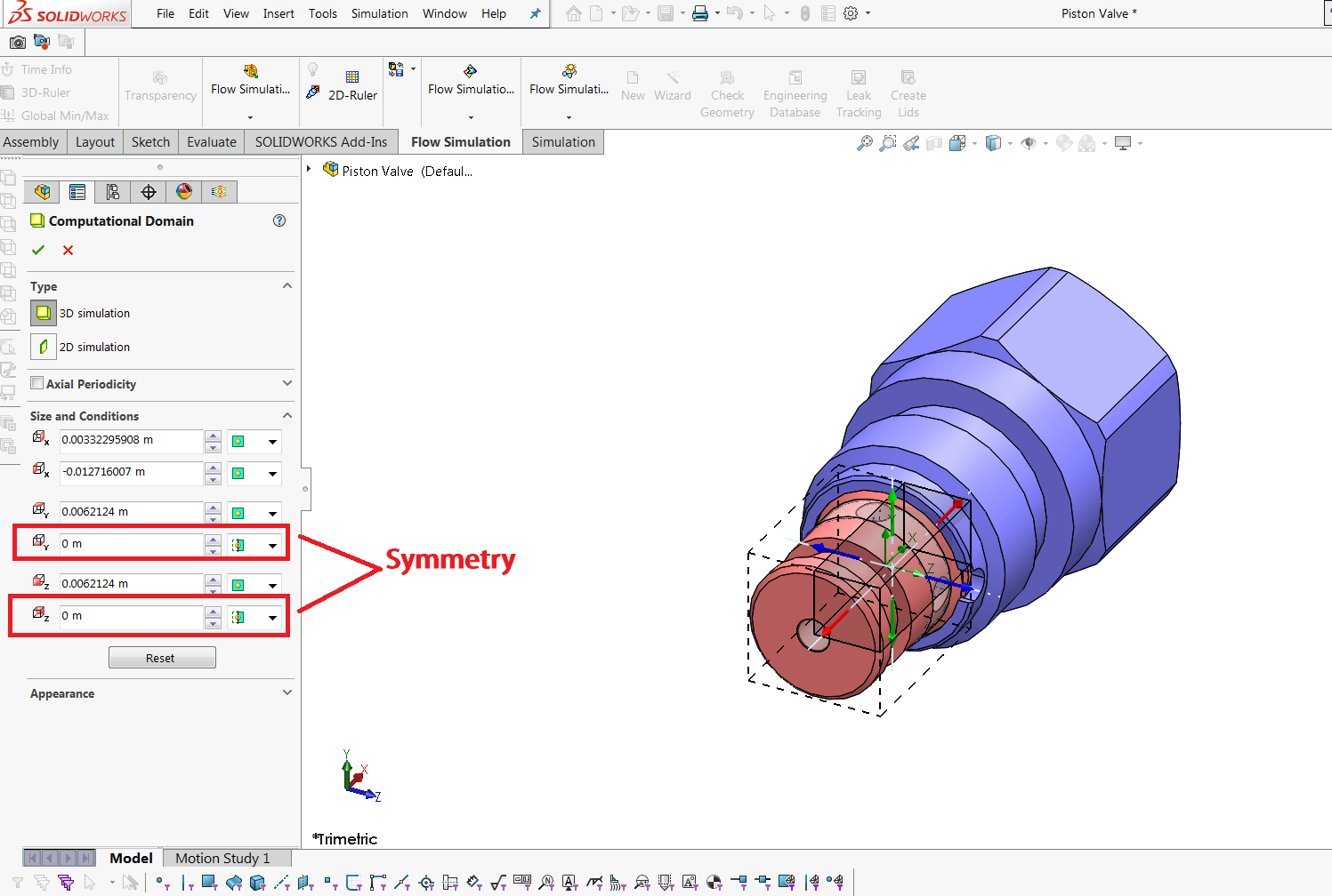
As an example the following picture shows a piston valve in which the water enters through the inlet in the center of the valve. Although these two computational domain boundary conditions are set up by editing the default computational. I am currently running SolidWorks Premium 2009 with Flow Simulation 2009.
Other types of structural loads are available via special functions like importing loads from SolidWorks Flow Simulation or SolidWorks Motion. SOLIDWORKS Flow Simulation 2016 has capabilities for solving various flow and thermal problems. An example of a vortex across a boundary would be directly from the first Flow Simulation tutorial in SOLIDWORKS the tutorials can be found under Help SOLIDWORKS Simulation Flow Simulation Online Tutorial once the Flow Simulation add-in is turned on.
It is related to the geometry of the model assuming the boundary conditions are done correctly. Hello I am seeking some general guidance on flow simulation in solidworks. SOLIDWORKS FloXpress remembers the initial selection in later calculations.
How to perform the Zooming technique aka Transferred Boundary Conditions From the Help. The Transferred Boundary Conditions allows you to focus on a specific region within your model by using results obtained in a previous Flow Simulation calculation as a boundary condition for the current Flow Simulation project. A few problem with a flow simulation solidworks forums.
In SolidWorks Flow Simulation I am trying to create boundary conditions such that I can run an internal flow analysis. SR By Sanjay Ramlall 052119. Usually when you receive the SOLIDWORKS Flow Simulation Error.
Taking advantage of geometric symmetry by making use of symmetry boundary conditions in SOLIDWORKS Flow Simulation is a highly recommended best-practice technique for speeding up your flow analysis runs. Getting the boundary conditions to correlate to actual scenario is challenge analysts face on a daily bases. Sets the temperature of the incoming fluid.
Solidworks Flow simulation Boundary condition question image included 1. Pdf solidworks tutorial beginner. Having 3D geometry and knowing how you want the product behave is only half the battle.
Hey everyone I need some help with the boundary conditions of this problem. Launch the Flow Simulation Wizard to get the analysis started. The length along any edge is 100 mm and the change in temperature is 100 C.
Taking advantage of geometric symmetry by making use of symmetry boundary conditions in SOLIDWORKS Flow Simulation is a highly recommended best-practice technique for speeding up your flow analysis runs. In order to use the symmetry in flow simulation both the geometry and the boundary conditions should be symmetric. A load or restraint is applied by the corresponding PropertyManager accessible by right-clicking the Fixtures or External Loads folder in the Simulation study tree or by clicking Simulation LoadsFixture.
The last boundary condition that I want to add is a temperature to the entire body of the cube 125 C. Symmetry and periodic boundary conditions in SOLIDWORKS Flow Simulation are used to reduce the size of the flow problem thereby reducing analysis run time. SOLIDWORKS Flow Simulation can be configured for symmetry periodicity or even planar flow to speed up the solution or to increase the mesh quality without impacting the accuracy of the flow results.
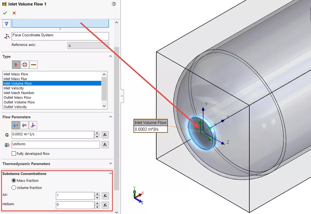
Solidworks flow simulation tutorial français 12 2020. SOLIDWORKS Flow Simulation creates mirrored results for symmetric studies. In the Mass Flow Rate box set a value.
The water tank you see here has some jets on the inside corners highlighted yellow and along some of the walls. The ball valve as it is setup in the tutorial. This option is also accessed locally in its corresponding property manager for the various pressure boundary conditions.
Look for edge-edge. Arrows from the face indicate the flow direction. Face to Apply Inlet Boundary Condition.
Flow Simulation Boundary Conditions. Page 1 Give the analysis a name. Pressure potential in SOLIDWORKS Flow Simulation is a simple check box in the initial conditions section of the projects general settings.
SOLIDWORKS Flow Simulation with less than 8 hours of training. Sets the face used for the inlet boundary.
Flow Simulation Basic Concepts Engineers Rule

Tutorial Applying Boundary Condition In Flow Simulation Grabcad Tutorials

Flow Simulation Basic Concepts Engineers Rule
Flow Simulation Basic Concepts Engineers Rule
How To View The Mirror Results In Solidworks Flow Simulation Seacad

Faster Results With Boundary Conditions
Solidworks Flow Simulation Fluid Mixing Tutorial Goengineer

Tutorial Applying Boundary Condition In Flow Simulation Grabcad Tutorials
![]()
What S New In Solidworks 2019 Simulation Flow Plastics
Solidworks 2017 Flow Simulation Youtube
Solidworks Flow Simulation Boundaries And Goals Youtube

Solidworks Flow Simulation Tutorial On Kaplan Turbine Youtube

Faster Results With Boundary Conditions

Solidworks Flow Simulation Archives
Flow Simulation Basic Concepts Engineers Rule
Faster Results With Boundary Conditions

Faster Results With Boundary Conditions

Faster Results With Boundary Conditions
Solidworks Flow Simulation 2020 Helps You Make Better Decisions For Superior Performance Cadalyst